Kart flex length: what a quarter and a half inch do to a 100 cc kart's power
WaveDyno tutorial 16, about 15 minutes plus four sweeps.
Ask a karting forum how flex length changes the power and the usual answer comes back. One X30 driver put it this way on KartPulse: "shortening my exhaust will give me more top end, or how lengthening it would give me more on the bottom end." A KT100 owner asked whether to change it in half-inch steps and was told "1/4" increments or less". None of the threads we read shows a curve. This guide makes the flex a quarter inch longer, half an inch longer and half an inch shorter on the app's 100 cc kart engine, sweeps each one and shows what moved. Every step is there for you to rerun.
The short answer, in this model, on this engine:
- A quarter inch longer gave more bottom end, and was never more than 0.03 kW behind from 12,000 to 17,750 rpm. It made 0.28 to 0.51 kW (1.3 to 2.9 %) more from 12,000 to 13,500 rpm, within 0.18 kW of the baseline from 13,750 to 15,250, and 0.20 to 0.93 kW more from 15,500 to 17,750. It came off the pipe sooner: between 18,000 and 18,250 rpm, where the baseline came off between 18,250 and 18,500.
- Half an inch longer did the same, about twice as strongly. It made 0.47 to 1.01 kW (2.1 to 6.0 %) more from 12,000 to 13,500, and up to 1.81 kW (7.6 %) more at 17,000. It came off the pipe sooner still, between 17,500 and 17,750.
- Half an inch shorter did the opposite. It made less at every point from 12,000 to 18,000 rpm, up to 1.24 kW (7.9 %) less at 12,000. In return it stayed on the pipe longer, to between 18,750 and 19,000.
So on this model, a longer flex didn't trade top end for bottom end where the runs can be compared (both on the pipe, at least 500 rpm below the first drop). There it made more at the bottom and near the top, gained least around 14,000 to 15,000 (a quarter inch was close to level there), and came off the pipe sooner. That's the over-rev karters talk about, and it's the part of the answer the model can say least about (section 4).
What the page can't answer:
- What flex your kart should run. The example is the app's kart archetype, a 100 cc air-cooled reed kart engine. It isn't a KT100, an X30, a KA100 or anyone's actual engine, and the model isn't calibrated against a dyno. A different engine or pipe can answer differently, by a different amount. The page says nothing about any class's rules either.
- What a real flex does that a cone doesn't. In the app the flex is the first section of the pipe, a gentle cone. A real flex is a straight, corrugated tube (section 1).
- Exactly how far a quarter inch moves the drop. The drop in this model depends on how the engine got there (section 4), so the page gives no "rpm per quarter inch" for over-rev.
- Jetting or heat. The model holds the mixture fixed. This page gives no advice on jetting or carburation, and it doesn't test whether a shorter flex runs hotter.
Everything here runs on WaveDyno's free plan with daily run limits. There are four full sweeps of 33 points. The Run dyno button showed 5.2 to 5.4 units for each, and a finished sweep is charged what it actually used, up to its estimate; ours were charged 3.3 or 3.4 units each. In our runs, on a day with nothing else run, all four fit in one day's allowance. The app refuses a run whose estimate doesn't fit in what's left of the day, so if you've already run something today, follow the remaining allowance the app shows. The cold start in section 4 is optional and smaller: 8 points, 1.1 units on the button. The limit resets at midnight UTC, and your runs stay in the project, so you can pick up where you stopped.
1. Where the flex is in the app
A kart pipe is a header from the port, a flex, then the chamber: diffuser, belly, baffle and stinger. In WaveDyno the exhaust is a table of sections on Build → Ducts, and the first row, header, runs from the exhaust port to the start of the diffuser. There's no row in front of it, and the + on a row inserts a section after it. So a flex change is a change to the header row's length, as in Compare two pipes, which lengthens a 125's header by 30 mm and explains the badges and Compare in full.
On this engine the header row is a cone, 38 mm at the port to 52 mm at the diffuser. Lengthen it and the app stretches that cone. A real flex is a straight tube of one diameter with a corrugated wall. So these runs show what moving the chamber away from the port by a quarter or half an inch does. They don't model the flex's own shape, its rough wall or its temperature.
Karters usually measure flex length from the piston face to the end of the flex: "8 inches from the piston to the end of the flex" for a KT100, "from the face of the piston" for a club minimum. The app's header row starts at the exhaust port. The change in length is the same either way; only the change carries over from these runs, not the absolute length.
A quarter inch is 6.35 mm. The field takes tenths of a millimetre, so this page uses 6.4 mm (215.0 → 221.4) for a quarter inch and 12.7 mm for half an inch. On this pipe, a quarter inch is 3.0 % of the header and 0.8 % of the whole pipe.
2. The engine
Create a new project with the setup wizard (the + button next to the project name, as in tutorial 1). Pick the archetype 100 cc air-cooled kart, keep every answer at its default, give the project a name and create it. It's the same engine as Crankcase compression: a 48.5 × 54 mm single (99.8 cc) with an ideal reed intake and an expansion chamber.
The wizard sets the dyno to 8,000–18,000 rpm in 500 rpm steps, which stops before this engine comes off the pipe. On Run → Setup, set From 12000, To 20000, Step 250, quality Standard, and leave the rest. That's 33 points, and it covers the top of the band and the drop. Keep it the same for every run here: Compare only shows a delta where both runs have the same rpm. These runs don't go below 12,000, so this page says nothing about lower rpm.
Check the pipe before you run. On Build → Ducts, the exhaust table's L mm column reads header 215.0, diffuser 195.0, belly 80.0, baffle 160.0, stinger 150.0, with the Throat orifice switch on, and the badges under it read 800 mm total and tuned ≈ 15300 rpm. Under Model calibration (advanced), Cell size Δx reads 10.00 mm; its tooltip says 65 cells. The Engine tab shows one note, about mean piston speed at 20,000 rpm. It's a durability note, it's there for every run on this page, and none of the changes here adds or removes a warning.
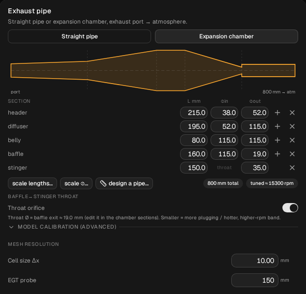
baseline: the five rows, the badges 800 mm total and tuned ≈ 15300 rpm, the Throat orifice switch on, and Cell size Δx 10.00 mm under Model calibration (advanced).Run the sweep, open Compare and name the run baseline. In ours every point converged. It builds from 15.60 kW at 12,000 rpm to its best point at 18,000, and comes off the pipe between 18,250 and 18,500 rpm, losing 61 % of its power in that one step. Crankcase compression shows the same baseline.
Before each change below, restore the baseline: Compare → the restore icon on baseline → Restore settings. Then check that Diff inputs against baseline is empty. Every change is made from the baseline, not from the run before it.
3. A quarter inch longer: 215.0 → 221.4 mm
On Build → Ducts, click the header row's L mm cell and change 215.0 to 221.4. Nothing else.
Check before you run:
- The badges read 806.4 mm total and tuned ≈ 15100 rpm.
- Compare → Diff inputs against
baselinelists one line:Exhaust / Sections #0 / Length, 0.215 → 0.2214 (in metres). The app keeps the cell size and recounts the cells for the longer pipe; here the count stays at 65, so it doesn't show. The half-inch runs below add a cell or take two away, and their Diff inputs show that as a second line,Num Elements.
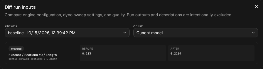
Run it, name it flex +quarter, and in Compare set baseline as the baseline.
| rpm | baseline kW | flex +quarter kW | change |
|---|---|---|---|
| 12,000 | 15.60 | 16.05 | +0.45 (+2.9 %) |
| 12,500 | 17.93 | 18.44 | +0.51 (+2.9 %) |
| 13,000 | 20.28 | 20.72 | +0.44 (+2.1 %) |
| 13,500 | 22.03 | 22.31 | +0.28 (+1.3 %) |
| 14,000 | 22.65 | 22.62 | −0.03 (−0.1 %) |
| 14,500 | 22.78 | 22.92 | +0.14 (+0.6 %) |
| 15,000 | 23.05 | 23.20 | +0.15 (+0.7 %) |
| 15,500 | 23.06 | 23.27 | +0.20 (+0.9 %) |
| 16,000 | 23.19 | 23.55 | +0.36 (+1.5 %) |
| 16,500 | 23.58 | 24.17 | +0.59 (+2.5 %) |
| 17,000 | 23.77 | 24.47 | +0.69 (+2.9 %) |
| 17,250 | 23.81 | 24.74 | +0.93 (+3.9 %) |
| 17,500 | 24.02 | 24.89 | +0.88 (+3.6 %) |
| 17,750 | 23.93 | 24.62 | +0.69 (+2.9 %) |
| 18,000 | 24.34 | 23.03 | (outside the comparison zone) |
| 18,250 | 23.83 | 9.42 | (one on the pipe, one off) |
| 18,500 | 9.36 | 9.18 | (both off the pipe) |
Italics: off the pipe. Every point of both runs converged. The CSV (the download icon in the chart header) has all 33 points.
What moved, reading where both runs are on the pipe and at least 500 rpm below the first drop (12,000 to 17,750):
- More at the bottom. Ahead at every point from 12,000 to 13,500, by 0.28 to 0.51 kW (1.3 to 2.9 %). That's the forums' "longer gives more bottom end", on this engine.
- Level through the middle. From 13,750 to 15,250 it was within 0.18 kW of the baseline, either way. At 14,000 it was 0.03 kW behind.
- More again near the top. From 15,500 to 17,750 it was ahead by 0.20 to 0.93 kW, most at 17,250.
- Then it comes off first. At 18,000 both are still on the pipe, but the longer flex is within 500 rpm of its drop, so the page doesn't compare them there. It comes off between 18,000 and 18,250; the baseline between 18,250 and 18,500.
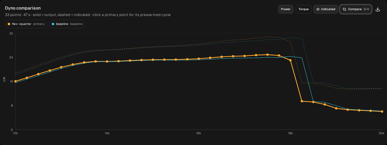
flex +quarter and baseline, with the same sweep settings.4. Half an inch longer: 215.0 → 227.7 mm
Restore baseline. Change the header's L mm from 215.0 to 227.7. Nothing else. The badges read 812.7 mm total and tuned ≈ 14900 rpm, and Diff inputs lists two lines: the header length 0.215 → 0.2277, and Num Elements 65 → 66. Run it and name it flex +half.
| rpm | baseline kW | flex +quarter | flex +half |
|---|---|---|---|
| 12,000 | 15.60 | +0.45 (+2.9 %) | +0.94 (+6.0 %) |
| 12,500 | 17.93 | +0.51 (+2.9 %) | +1.01 (+5.6 %) |
| 13,000 | 20.28 | +0.44 (+2.1 %) | +0.79 (+3.9 %) |
| 13,500 | 22.03 | +0.28 (+1.3 %) | +0.47 (+2.1 %) |
| 14,000 | 22.65 | −0.03 (−0.1 %) | +0.09 (+0.4 %) |
| 15,000 | 23.05 | +0.15 (+0.7 %) | +0.33 (+1.4 %) |
| 16,000 | 23.19 | +0.36 (+1.5 %) | +0.84 (+3.6 %) |
| 16,500 | 23.58 | +0.59 (+2.5 %) | +1.41 (+6.0 %) |
| 17,000 | 23.77 | +0.69 (+2.9 %) | +1.81 (+7.6 %) |
| 17,250 | 23.81 | +0.93 (+3.9 %) | +1.58 (+6.6 %) |
| 17,500 | 24.02 | +0.88 (+3.6 %) | (outside the comparison zone) |
| 17,750 | 23.93 | +0.69 (+2.9 %) | off the pipe |
Changes against baseline, in kW. Every point converged.
- The second quarter inch added about as much as the first. From 12,000 to 13,250, the half-inch gain was 1.8 to 2.1 times the quarter-inch one.
- Ahead at every point while both were on the pipe (12,000 to 17,250, at least 500 rpm below its drop), by 0.09 to 1.81 kW. The smallest gains are again around 14,000; the largest, 1.81 kW (7.6 %), is at 17,000.
- Off the pipe sooner, between 17,500 and 17,750.
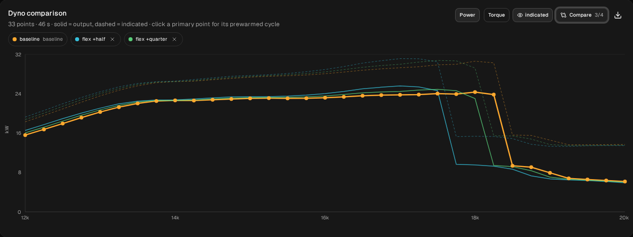
baseline, flex +quarter and flex +half, with the same sweep settings.Why the drop matters more than the numbers
Each run comes off the pipe in one step: between one 250 rpm point and the next, power falls by 59 to 61 %, from 23.0 to 24.6 kW to 9.3 to 9.7 kW. The order is clear: the longer the flex, the sooner it comes off. How far it moves for a quarter inch, the model can't tell you, for two reasons.
- A 250 rpm step can only bracket it. Between "on" at one point and "off" at the next, the drop could be anywhere.
- Where the engine comes off depends on how it got there. The app runs a sweep upwards and starts each point from the state the one before it left. So we ran the baseline again from 18,250 up, starting cold (Run → Setup, From 18250; Diff inputs lists only
Sweep / Rpm Min). At 18,250 it settled at 9.50 kW, off the pipe, where the rising sweep made 23.83. From 18,500 up the two agreed within 0.12 kW. Both results at 18,250 are marked converged. Only the first point of a sweep starts cold, so this is one comparison at one rpm, and it doesn't show where a cold engine comes off the pipe. It does show that at the edge this model gives two different answers depending on how the engine got there.
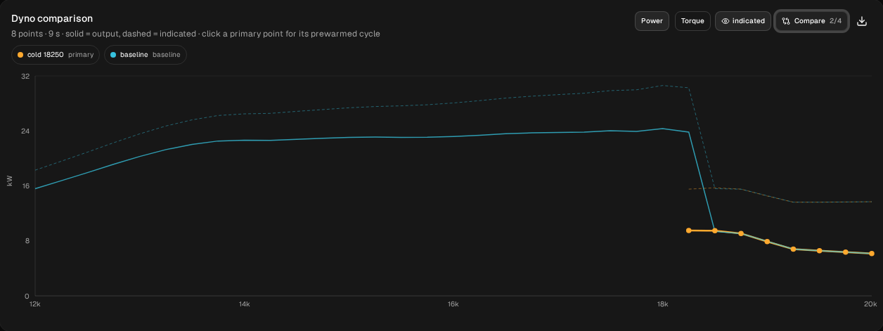
cold 18250 (18,250 to 20,000 rpm, started cold) and baseline (swept up from 12,000).And at the finest mesh we've tried on this engine (2 mm cells against the default 10), the baseline's 18,000 rpm point was already off the pipe. So the brackets in this guide say which run comes off first on this mesh and sweep, not at what rpm a real engine will stop pulling. Pipe temperature shows the same kind of edge on the moto-X engine.
5. Half an inch shorter: 215.0 → 202.3 mm
Restore baseline. Change the header's L mm from 215.0 to 202.3. Nothing else. The badges read 787.3 mm total and tuned ≈ 15600 rpm, and Diff inputs lists the header length 0.215 → 0.2023 and Num Elements 65 → 63. Run it and name it flex -half.
| rpm | baseline kW | flex -half kW | change |
|---|---|---|---|
| 12,000 | 15.60 | 14.36 | −1.24 (−7.9 %) |
| 13,000 | 20.28 | 19.12 | −1.16 (−5.7 %) |
| 14,000 | 22.65 | 22.38 | −0.27 (−1.2 %) |
| 15,000 | 23.05 | 22.71 | −0.34 (−1.5 %) |
| 16,000 | 23.19 | 22.68 | −0.52 (−2.2 %) |
| 17,000 | 23.77 | 22.48 | −1.29 (−5.4 %) |
| 17,750 | 23.93 | 22.24 | −1.69 (−7.1 %) |
| 18,000 | 24.34 | 22.67 | −1.67 (−6.9 %) |
| 18,250 | 23.83 | 23.30 | (outside the comparison zone) |
| 18,500 | 9.36 | 23.62 | (one on the pipe, one off) |
| 18,750 | 9.08 | 23.36 | (one on the pipe, one off) |
| 19,000 | 7.93 | 9.35 | (both off the pipe) |
Italics: off the pipe. Every point of both runs converged.
- Less everywhere it could be compared. From 12,000 to 18,000 it was behind at every point, by 0.13 to 1.69 kW: most at the bottom (7.9 % at 12,000) and near the top (7.1 % at 17,750), least from 14,000 to 15,500 (0.13 kW at 14,250).
- On the pipe longer. It came off between 18,750 and 19,000, after the baseline.
So on this model the shorter flex cost power at every point the runs can be compared, most at the bottom, and it stayed on the pipe longer. The page doesn't put a power figure on those extra points: they sit at the edge, where this model's answer depends on how the engine got there (section 4).
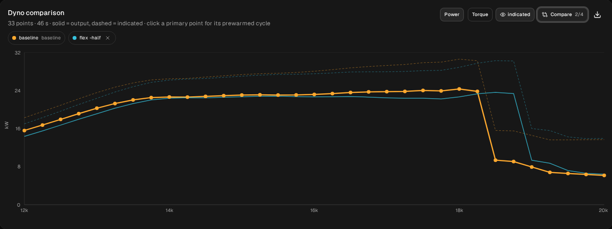
flex -half and baseline, with the same sweep settings.All four runs
| Run | header L mm | Against baseline, where both are on the pipe | Comes off the pipe between |
|---|---|---|---|
flex -half | 202.3 | −0.13 to −1.69 kW, 12,000 to 18,000 | 18,750 and 19,000 |
baseline | 215.0 | 18,250 and 18,500 | |
flex +quarter | 221.4 | +0.28 to +0.51 kW at 12,000–13,500; within 0.18 at 13,750–15,250; +0.20 to +0.93 at 15,500–17,750 | 18,000 and 18,250 |
flex +half | 227.7 | +0.47 to +1.01 kW at 12,000–13,500; +0.09 to +1.81 at 12,000–17,250 | 17,500 and 17,750 |
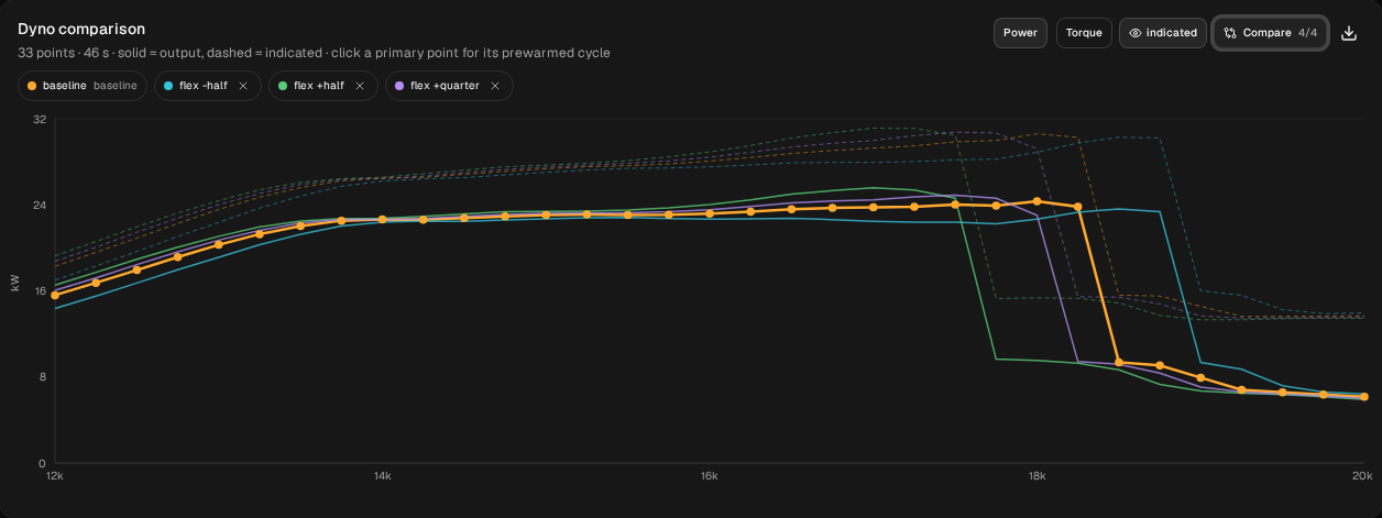
baseline, flex +quarter, flex +half and flex -half, with the same sweep settings.These runs use the app's default mesh. On this engine, away from the drop and on the grid tested (8,000 to 18,000 rpm in 500 rpm steps), power at each rpm moves by up to about 4 % between 8 mm and 4 mm cells, and by less again between 4 mm and 2 mm. At the drop the mesh can decide whether a point is on the pipe at all (section 4). That's why this page gives differences rather than a peak figure. Every run here uses the same mesh, so the comparisons are like for like. The quarter-inch changes (up to 3.9 %) are about the size of that mesh effect on absolute power, and we haven't repeated the comparisons on a finer mesh, so take their size as what the default mesh shows.
What to take from it
On this model, with this engine, changing only the header length:
- Longer gave more bottom end, as the forums say: a quarter inch added up to 2.9 % from 12,000 to 13,500, and half an inch about twice that.
- Longer was ahead at the bottom and near the top, and gained least in between, where the runs can be compared: to 17,750 rpm for a quarter inch and 17,250 for half an inch. A quarter inch longer was within 0.18 kW of the baseline from 13,750 to 15,250 and never more than 0.03 kW behind; half an inch longer was ahead at every point, by 0.09 kW at the least. What they gave up was the top of the rev range: each came off the pipe sooner.
- Half an inch shorter cost power at every point from 12,000 to 18,000 rpm and held the pipe longer.
- The drop's position is the soft part of the answer. It's ordered by length, but its rpm depends on the sweep, the mesh and how the engine got there.
Those are answers for one engine that you can check, not rules. To get them for yours:
- Enter your own engine with the setup wizard, sweep it across its drop, then change only the header's L mm, a quarter inch at a time, from the same baseline. Check with Diff inputs before you run: the length, and maybe the cell count.
- Compare at the same rpm, with the baseline set, as Compare two pipes shows.
- Treat any drop as a bracket. If over-rev is what you're tuning for, the track and a real dyno will tell you more than this model can.
- For why length moves the tune, How an expansion chamber works explains what the waves in the pipe are doing, and Tune a moped pipe lengthens a whole pipe instead of one section.
If you've run two flex lengths on the same engine and have dyno sheets for both, join the tester programme. That comparison is what we most want to see.
These are simulated estimates from a 1D gas-dynamics model of a generic engine, not measurements, and not your engine. The model isn't calibrated against a dyno, and even the differences between the runs hold only for this model. Its flex is a lengthened cone, not a straight corrugated tube; its reed is the app's ideal valve; and it holds the mixture fixed. The model shows falling off the pipe as a sharp step, sharper than a real dyno, and where the step lands can depend on how the engine got there. Nothing here says how a kart will drive or race. Use WaveDyno to compare designs and to understand what the pipe is doing. See the Terms of Service, section 4.