Stinger size on a two-stroke pipe: what a bigger stinger does to power and heat, and does length matter?
WaveDyno tutorial 14, about 15 minutes plus five sweeps, over at least two days on the free plan.
The stinger is the small tube at the end of an expansion chamber. Ask how big or how long it should be and you get rules of thumb, and they don't agree on which way to go. None of the sources we read has a length chart. This guide changes the stinger end of a simulated 125 one step at a time: bigger, smaller, then longer. It sweeps each version and shows what moved, with every step there for you to rerun.
The short answer, in this model, on this engine:
- A bigger stinger end ran cooler and gave up the top. We widened the throat and the stinger bore by 8 %. The exhaust gas was 11 to 51 °C cooler at the probe everywhere both runs were on the pipe. Power was 0.65 kW (3.6 %) up at 10,000 rpm, level by 10,500, and 0.16 to 1.10 kW (4.1 %) down from 10,750 to 12,750. The engine came off the pipe between 12,750 and 13,000 rpm; the template pipe holds on to 13,500.
- A smaller one did the opposite. It cost 1.09 kW (6.0 %) at 10,000, gained up to 2.27 kW (9.0 %) at 13,500 and stayed on the pipe to 14,000. The exhaust gas ran 21 to 101 °C hotter.
- Length hardly mattered. Doubling the stinger to 100 mm, or making it six times as long at 312 mm, moved power by tenths of a kW over most of the band and never ran the exhaust gas more than 9 °C hotter. The clearest change was at 10,000 rpm.
What the page can't answer:
- What size your stinger should be. WaveDyno treats the step into the stinger as having no length, and that has a known limit (section "How the model sees the stinger"). So the results here are directions and rough sizes on one model engine, not a size for a real pipe.
- What your engine will do. The example is the app's 125 moto-X archetype, the engine of tutorials 1, 4, 9, 10, 11 and 13. It isn't anyone's actual bike, and the model isn't calibrated against a dyno. A different engine can answer differently: on the 50 cc moped of tutorial 3, a bigger stinger barely moved anything (more in section 2).
- Jetting. The model holds the mixture fixed, so every run here has the same mixture; it doesn't model a change in carburation, and this page gives no advice on jetting or carburation.
Everything here runs on WaveDyno's free plan with daily run limits. There are five full sweeps of 19 points. The Run dyno button showed 15.8 to 17.7 units for each, and a finished sweep is charged what it actually used, up to its estimate. In our runs that was 6.7 to 14.3 units a sweep. Expect to need at least two UTC days. The app refuses a run whose estimate doesn't fit in what's left of the day. With our observed charges, in the order of this page, the fourth sweep would exceed the first day's allowance; with yours the refusal can come at a different sweep, so follow the remaining allowance the app shows. The limit resets at midnight UTC, and your runs stay in the project, so you can pick up where you stopped.
What the rules of thumb say
Two written sources, read at the source:
- Wikipedia's Expansion chamber article gives the stinger's inside diameter as "0.59 to 0.63x the header pipe diameter", and says "its length is equal to 12 times its diameter, depending on the results to be achieved". It warns that a wrong size "will lead either to poor performance (too big or too short) or to excessive heat (too small or too long)". It cites no source for either figure.
- Eric Murray's "How Two-Stroke Expansion Chambers Work, and Why You Should Care" (copy on qsl.net) says back pressure "caused by a smaller-diameter or longer stinger section" can "increase the engine's performance", and that "it also causes the engine to run hotter".
The app has its own rule of thumb, in two places. The pipe calculator's Power level tooltip reads: "Smaller stinger = stronger plugging, hotter and peakier; larger = broader and cooler." And the Throat orifice note under the Ducts table says: "Smaller = more plugging / hotter, higher-rpm band."
On this engine's 40 mm header, Wikipedia's ratio gives 23.6 to 25.2 mm. The template's throat is 23.5 mm and its stinger bore 26.0 mm. Twelve diameters of a 26 mm stinger is 312 mm, and the template's is 50 mm. Section 3 tries that length.
None of these sources has a curve you can rerun. This guide sets its results beside them; it doesn't claim to confirm them.
How the model sees the stinger
Go to Build → Ducts. The template pipe has five rows:
| Row | L (mm) | ⌀ in (mm) | ⌀ out (mm) |
|---|---|---|---|
| header | 265.0 | 40.0 | 45.0 |
| diffuser | 210.0 | 45.0 | 100.0 |
| belly | 100.0 | 100.0 | 100.0 |
| baffle | 218.0 | 100.0 | 23.5 |
| stinger | 50.0 | throat | 26.0 |
The badges read 843 mm total and tuned ≈ 12900 rpm.
The Throat orifice switch is on in the template; How an expansion chamber works shows what it changes in the wave diagram and the mesh. With it on, the narrowest point is the baffle's exit, 23.5 mm: that's the throat. The stinger after it is a straight tube at its ⌀ out, 26.0 mm, so its ⌀ in cell reads throat. The table won't let the baffle's exit be wider than the stinger, or the stinger narrower than the baffle's exit.
WaveDyno treats the step from the baffle into the stinger as having no length: the gas goes from one pipe to the next in a single junction. The app's validation case for that junction (V2) checks it against a stored CFD run of a sharp plate and a short venturi:
- Steady flow when the throat is choked (the regime of exhaust blowdown) comes within 3.4 % of the CFD.
- A sudden pressure front hitting it is harder. The junction can't produce the short reflected spike the CFD shows. It gets the sustained reflection that follows to about a factor of two, in the right order between the two shapes.
That's why this page reports directions and rough sizes, not exact figures, and recommends no stinger size for a real pipe.
The engine
Create a new project with the setup wizard (the + button at the top, as in tutorial 1), pick 125 moto-X / enduro, keep every answer at its default and create it. On Run → Setup, set the sweep to 10,000 to 14,500 rpm in 250 rpm steps, quality Standard. Keep it the same for every run here.
Run the sweep, open Compare and name the run baseline. This is the baseline of Raise the exhaust port, which walks through it: 18.33 kW at 10,000 rpm, a highest sampled point of 27.13 kW (36.4 hp) at 13,000, then off the pipe between 13,500 and 13,750.
Before each change below, restore the baseline: Compare → the restore icon on baseline → Restore settings. Then check that Diff inputs against baseline is empty. Every change is made from the baseline, not from the run before it.
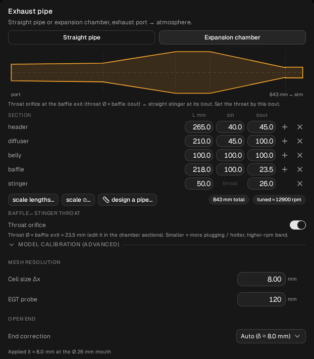
baseline: the five rows, the badges 843 mm total and tuned ≈ 12900 rpm, and the Throat orifice switch on.1. A bigger stinger end
The calculator's Power level does this kind of change: Mild multiplies the baffle exit and the stinger bore by 1.08. It also rounds them to the whole millimetre and rebuilds the pipe, so here you type the two numbers yourself and nothing else moves.
On Build → Ducts, change the stinger's ⌀ out from 26.0 to 28.1, then the baffle's ⌀ out from 23.5 to 25.4. Type them in that order, so the baffle never ends up wider than the stinger.
Check before you run:
- The badges still read 843 mm total and tuned ≈ 12900 rpm, and the tooltip on Cell size Δx (in Model calibration) still reads 99 cells. The tuned-rpm estimate is set by the lengths, and they haven't changed.
- The stinger's ⌀ in still reads throat.
- Compare → Diff inputs against
baselinelists two lines:Exhaust / Sections #3 / D Out0.0235 → 0.0254 andExhaust / Sections #4 / D Out0.026 → 0.0281. (The sections count from 0, in metres.) - One thing changes by itself: the open-end note in Model calibration goes from "δ ≈ 8.0 mm at the Ø 26 mm mouth" to "δ ≈ 8.6 mm at the Ø 28 mm mouth". The automatic end correction follows the stinger's mouth. It isn't an input, so Diff inputs doesn't list it.
Run it, name it stinger x1.08, and in Compare set baseline as the baseline. Switch the lower chart to EGT.
| rpm | baseline kW | stinger x1.08 kW | change | EGT change at the probe |
|---|---|---|---|---|
| 10,000 | 18.331 | 18.984 | +0.653 (+3.6 %) | −21.8 °C |
| 10,250 | 20.989 | 21.210 | +0.221 (+1.1 %) | −13.1 °C |
| 10,500 | 22.329 | 22.338 | +0.009 (0.0 %) | −13.3 °C |
| 11,500 | 24.550 | 24.267 | −0.283 (−1.2 %) | −14.7 °C |
| 12,250 | 26.314 | 26.021 | −0.293 (−1.1 %) | −44.0 °C |
| 12,500 | 26.845 | 26.182 | −0.663 (−2.5 %) | −49.1 °C |
| 12,750 | 27.086 | 25.986 | −1.100 (−4.1 %) | −51.0 °C |
| 13,000 | 27.129 | 13.450 | (off the pipe) |
Italics: off the pipe. Every point of both runs converged.
What moved, reading only where both runs are on the pipe (10,000 to 12,750):
- Cooler everywhere. The exhaust gas at the probe was 10.9 to 51.0 °C cooler at every point, most at the top of the band.
- A little more at the very bottom, less above it. It was up 0.65 kW at 10,000 and 0.22 at 10,250, and within 0.01 kW at 10,500. From 10,750 to 12,750 it was behind at every point, by 0.16 to 0.29 kW to 12,250, then 0.66 at 12,500 and 1.10 at 12,750. Its highest sampled point was 26.18 kW (35.1 hp) at 12,500, against the template's 27.13 kW (36.4 hp) at 13,000.
- More through, less kept. The delivery ratio was higher at every point: more fresh mixture went through the engine. But from 10,500 up, less gas stayed in the cylinder: 0.31 mg less at 10,500, rising to 5.52 mg less at 12,750. That's the pattern the tooltip's word "plugging" points at, weaker with a bigger stinger: more mixture through, less of it kept. These runs show it in the cylinder; they don't show the wave that does it.
- Off the pipe sooner. It came off between 12,750 and 13,000 rpm, where the template pipe stays on to 13,500.
Read that last point as a bracket, not an exact rpm. The model shows falling off the pipe as a sharp step, about half the power in one 250 rpm step. And near the top of the band this engine can run two ways. In Pipe temperature, section 3, the template pipe started cold at 13,000 is off the pipe, though the sweep from 10,000 is on it up to 13,500. So where a rising sweep leaves the pipe depends partly on how it got there. Here the move is three steps, and the bigger end is behind from 10,750 up, which the edge doesn't explain.
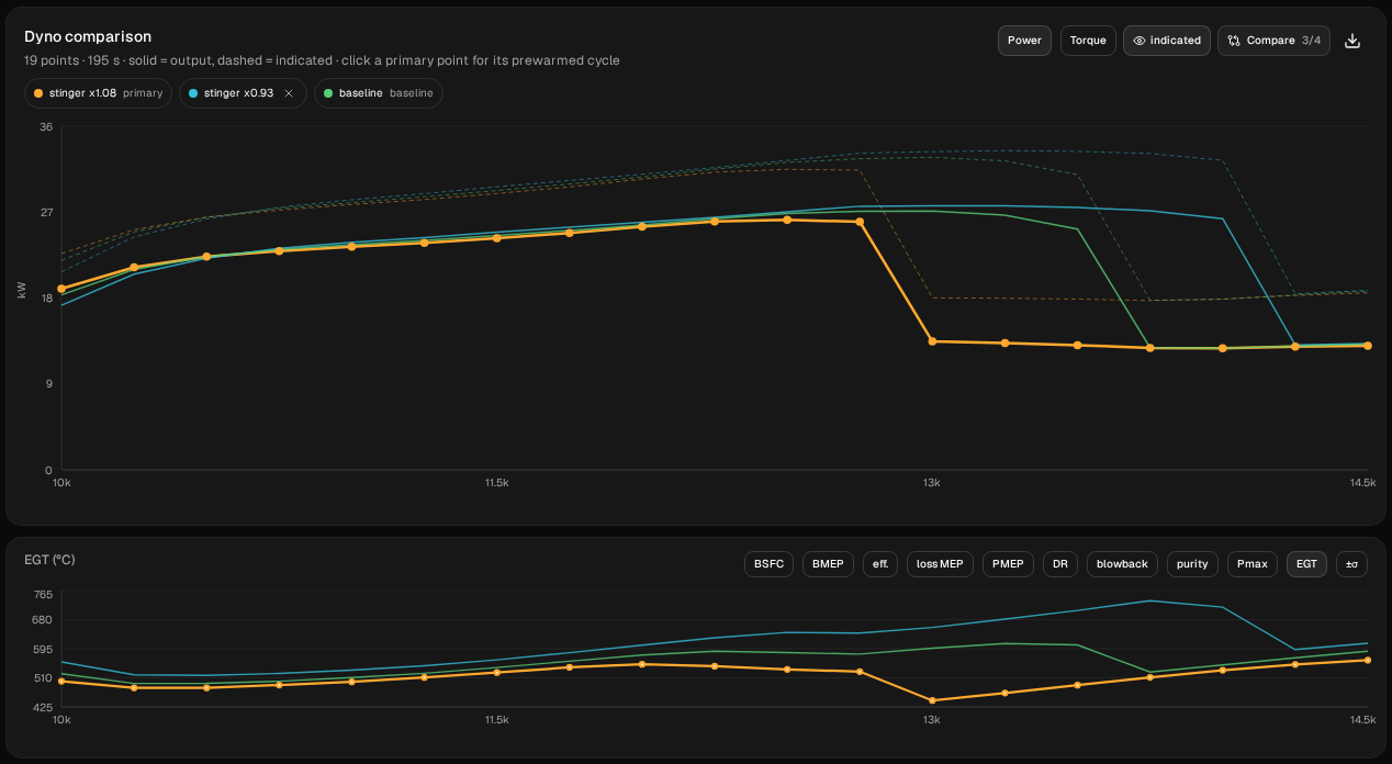
stinger x1.08, stinger x0.93 and baseline, with the lower chart on EGT.2. A smaller stinger end
Restore baseline. Change the baffle's ⌀ out from 23.5 to 21.9, then the stinger's ⌀ out from 26.0 to 24.2 (the baffle first this time, for the same reason). That's both by 0.93, the calculator's Max. Diff inputs lists the same two lines, to 0.0219 and 0.0242. The badges don't move, and the open-end note reads δ ≈ 7.4 mm at the Ø 24 mm mouth. Run it and name it stinger x0.93.
Tutorial 9, step 4 already ran this end with the calculator's Max. That pipe had the diameters rounded to 22.0 and 24.0 mm. Typed by hand without the rounding, the result is the same to within 0.03 kW at every point that page quotes:
- −1.094 kW at 10,000 (tutorial 9: −1.093);
- +2.266 kW at 13,500 (+2.292);
- on the pipe at 13,750 and 14,000, at 27.149 and 26.319 kW (27.168 and 26.336);
- off the pipe between 14,000 and 14,250.
So the calculator's rounding wasn't what drove that result. Tutorial 9 walks through this end in full; in short, on this engine:
- Hotter everywhere. The exhaust gas was 21.4 to 100.5 °C hotter at the probe at every point from 10,000 to 13,500.
- Less at the bottom, more at the top. It was behind by 1.09 kW at 10,000, 0.49 at 10,250 and 0.17 at 10,500. From 10,750 it was ahead at every point: by 0.12 to 0.54 kW up to 13,000, then 0.99 at 13,250 and 2.27 kW at 13,500. Its highest sampled point was 27.67 kW (37.1 hp) at 13,000, effectively tied with 13,250 (27.670 and 27.669 kW in the CSV), the point tutorial 9 names for its Max run. A finer sweep would be needed before reading any shift in the peak rpm.
- The mirror image of the bigger end. The delivery ratio was lower at every point, but from 10,750 up more gas stayed in the cylinder: 1.09 mg more at 10,750, rising to 11.47 mg more at 13,500.
What's new is the bigger end beside it. On this engine the two directions trade the same things the other way round: the bottom of the sweep against the top, and heat against both.
That isn't what tutorial 3, step 8 found on its 50 cc moped. There a bigger stinger moved nothing by more than 0.12 hp. That run widened only the stinger tube, behind an unchanged throat, on a different engine. Here the throat and the tube both change. This page doesn't separate which of the two did the work. It shows that on this 125 the pair of them moved the band, and that the 50 cc result doesn't carry over.
| rpm | baseline | stinger x1.08 | stinger x0.93 |
|---|---|---|---|
| 10,000 | 18.331 kW, 522.1 °C | 18.984 kW, 500.3 °C | 17.237 kW, 556.4 °C |
| 11,500 | 24.550, 540.1 | 24.267, 525.4 | 24.909, 562.4 |
| 12,500 | 26.845, 583.8 | 26.182, 534.7 | 27.034, 642.6 |
| 13,000 | 27.129, 596.8 | 13.450, 443.7 | 27.670, 657.2 |
| 13,500 | 25.219, 606.3 | 13.061, 488.6 | 27.485, 706.8 |
| 14,000 | 12.732, 547.7 | 12.749, 532.1 | 26.319, 716.6 |
Italics: off the pipe. Exhaust-gas temperature is at the model's probe, 120 mm down the header. It's the gas, not the pipe wall: Pipe temperature explains the difference and how the wall model works.
3. Does length matter?
Restore baseline. Change the stinger's L from 50.0 to 100.0, nothing else.
- 893 mm total, but still tuned ≈ 12900 rpm. The tuned-rpm estimate is measured from the port to the middle of the baffle, so it ignores the stinger.
- The Cell size Δx tooltip still reads 99 cells, because the main pipe ends at the baffle. With the throat on, the solver meshes the stinger as its own short pipe at the same spacing, with at least 12 cells, so a longer stinger gets more cells. The estimate on the button went from 16.6 to 15.8 units.
- Diff inputs: one line,
Exhaust / Sections #4 / Length0.05 → 0.1.
Run it and name it stinger L100. Then restore baseline again, set L to 312.0 (twelve diameters, Wikipedia's rule), and check: 1105 mm total, tuned ≈ 12900, 99 cells, one Diff line to 0.312. The button showed 17.7 units. Run it and name it stinger L312.
| rpm | baseline | stinger L100 | stinger L312 |
|---|---|---|---|
| 10,000 | 18.331 kW, 522.1 °C | 19.484 kW (+1.153), 491.1 °C | 18.814 kW (+0.483), 506.1 °C |
| 10,250 | 20.989, 493.5 | 21.350 (+0.361), 481.9 | 20.956 (−0.033), 478.5 |
| 11,500 | 24.550, 540.1 | 24.525 (−0.025), 538.5 | 24.687 (+0.137), 538.2 |
| 12,250 | 26.314, 587.8 | 26.025 (−0.289), 578.1 | 26.209 (−0.105), 582.7 |
| 13,000 | 27.129, 596.8 | 27.592 (+0.463), 600.0 | 27.249 (+0.120), 600.5 |
| 13,250 | 26.678, 610.3 | 27.195 (+0.517), 614.7 | 25.954 (−0.724), 593.7 |
| 13,500 | 25.219, 606.3 | 25.527 (+0.308), 612.1 | 13.320, 497.2 |
| 13,750 | 12.795, 526.9 | 13.337, 528.1 | 12.908, 518.5 |
Italics: off the pipe. Every point of all three runs converged.
What moved:
- At 10,000 rpm, both longer stingers made more: 1.15 kW (6.3 %) at 100 mm and 0.48 kW (2.6 %) at 312 mm. The longer of the two gained less, so on this engine the bottom of the sweep doesn't keep improving with length.
- Across the rest of the band, a few tenths. From 10,250 to 13,000:
- at 100 mm, power was within 0.36 kW of the template's from 10,250 to 12,500, and 0.46 to 0.49 kW up at 12,750 and 13,000 (0.52 at 13,250);
- at 312 mm, it was within 0.14 kW at every point.
Over the same points, the bigger stinger end in section 1 moved power by up to 1.10 kW.
- Not hotter. At 100 mm the exhaust gas was within 9.7 °C of the template's from 10,500 up (8.8 °C at most on the hot side), and cooler below that. At 312 mm no point on the pipe was more than 3.7 °C hotter, and from 10,000 to 11,000 it was 11 to 16 °C cooler. So on this engine, six times the length didn't produce the heat the rules of thumb warn about.
- The fall-off. At 100 mm, between 13,500 and 13,750, the same as the template. At 312 mm, one step earlier, between 13,250 and 13,500. One step on this edge is within what the sweep's own history can move (see section 1), so this page doesn't read it as an effect of length.
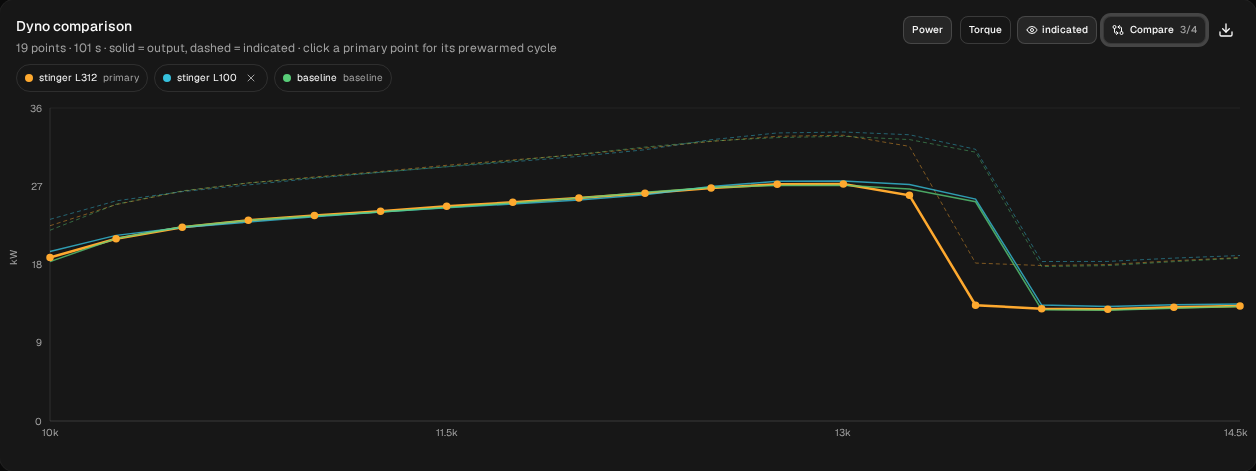
stinger L312, stinger L100 and baseline, with the same sweep settings.
These runs use the app's default mesh. The stinger's own cell count changes with its length (12 cells at 50 mm, the minimum, and more at 100 and 312), so part of the small differences in this section can be the mesh, not the stinger.
All five runs
| Run | Throat / stinger bore (mm) | Stinger L (mm) | Highest sampled point | Falls off the pipe between | EGT at the probe, against baseline, where both are on the pipe |
|---|---|---|---|---|---|
baseline | 23.5 / 26.0 | 50 | 27.13 kW (36.4 hp) at 13,000 | 13,500 and 13,750 | |
stinger x1.08 | 25.4 / 28.1 | 50 | 26.18 kW (35.1 hp) at 12,500 | 12,750 and 13,000 | 10.9 to 51.0 °C cooler |
stinger x0.93 | 21.9 / 24.2 | 50 | 27.67 kW (37.1 hp) at 13,000, tied with 13,250 | 14,000 and 14,250 | 21.4 to 100.5 °C hotter |
stinger L100 | 23.5 / 26.0 | 100 | 27.59 kW (37.0 hp) at 13,000 | 13,500 and 13,750 | 31.0 °C cooler to 8.8 °C hotter |
stinger L312 | 23.5 / 26.0 | 312 | 27.25 kW (36.5 hp) at 13,000 | 13,250 and 13,500 | 16.6 °C cooler to 3.7 °C hotter |
What to take from it
On this model, with this pipe:
- The stinger end's diameter moved the band; its length barely did. An 8 % bigger throat and stinger, or a 7 % smaller pair, moved power by up to 1.1 and 2.3 kW on the pipe and moved the fall-off by steps. Making the stinger two or six times as long moved power mostly by tenths of a kW.
- Bigger ran cooler and gave up the top. It was a little stronger at the very bottom of the sweep, weaker from 10,750 up, and off the pipe sooner.
- Smaller ran hotter and held the top. It was weaker at the bottom, stronger near the top, and on the pipe longer, which matches tutorial 9's Max.
- The rules of thumb on diameter point the way these runs went on heat; "too big" losing performance held only from 10,750 up here. On length, these runs didn't show the extra heat they warn about.
Those are answers for one engine that you can check, not rules. To get them for yours:
- Enter your own engine and pipe, then change the stinger end by a few percent each way, typed by hand, one change at a time from the same baseline. Check with Diff inputs before you run.
- Read the EGT chart with the power chart. The stinger end moved heat as much as power.
- Treat any fall-off as a bracket. Before you believe a change moved it, start short sweeps from the same rpm near the drop, as in Pipe temperature, section 3.
If you've built two stingers for the same pipe and have dyno sheets for both, join the tester programme. That comparison is what we most want to see.
These are simulated estimates from a 1D gas-dynamics model of a generic engine, not measurements, and not your engine. The model isn't calibrated against a dyno, and even the differences between the runs hold only for this model. It treats the step into the stinger as having no length, which gets steady choked flow close but a sudden pressure front only roughly. It holds the mixture fixed, and it knows nothing about piston temperature or seizure. The model shows falling off the pipe as a sharp step, sharper than a real dyno, and where the step lands can depend on the direction of the sweep. Use WaveDyno to compare designs and to understand what the port and the pipe are doing. See the Terms of Service, section 4.